EN
EN


What Is a Steam Trap? Principles, Types, and How to Select the Right Steam Trap for Your Steam System
Tutorial Videos on the DIVI Channel
A steam trap is a device that retains steam and discharges condensate, helping the steam system operate stably and save fuel. Understanding what a steam trap is, its role in heat exchangers, and the critical locations where it must be installed will help businesses avoid steam loss, optimize costs, and improve overall system efficiency.
Nội Dung Bài Viết
I. What is a steam trap? Its critical role and mandatory installation points in a steam system
1. Definition of a steam trap (retaining steam – discharging condensate – venting air)
A steam trap is a device that retains steam in the system to make maximum use of its energy, while automatically discharging condensate and non-condensable gases. When steam transfers heat to equipment and condenses into water, the steam trap opens to discharge this condensate, preventing accumulation and loss of efficiency. Conversely, when high-velocity, high-pressure steam is present, the trap closes to prevent steam loss. Thanks to its three functions—retaining steam, discharging condensate, and venting air—the steam trap helps the steam system operate stably, save energy, and protect equipment.
2. Principle of operation of a steam trap
A steam trap operates based on the differences between steam and condensate in terms of temperature, density, pressure, or liquid level. When steam transfers heat and condenses into water, the trap automatically opens to discharge condensate and non-condensable gases. When high-temperature, high-pressure steam reaches the trap, it closes to retain steam in the equipment, ensuring complete heat transfer. Through this automatic open–close cycle, the steam trap prevents waterlogging, minimizes steam loss, and maintains stable heat-transfer efficiency.
3. Role in heat exchangers
In a heat exchanger, steam from the boiler enters and transfers heat to another medium such as water, air, or oil. Once it has released its heat, the steam condenses into water. At this point, the steam trap plays a critical role: it retains steam to continue the heat-exchange process and only discharges condensate when necessary. This ensures that the heat energy in the steam is used to the fullest. If no steam trap is installed, both steam and condensate will escape continuously, causing severe steam loss, higher fuel consumption, and reduced equipment efficiency. The steam trap is therefore a mandatory component for economical and stable operation.
4. Impact on efficiency and fuel consumption
A steam trap directly affects the efficiency of heat exchangers and the fuel consumption of the entire system. When the trap operates correctly, condensate is discharged in time, keeping heat-transfer surfaces dry and clean, while steam is retained to maximize heat transfer. As a result, equipment heats up faster and more steadily, and the steam demand is significantly reduced. If the trap is faulty or the wrong type is selected, condensate accumulates and steam losses increase. The boiler must burn more fuel to compensate for the lost energy, driving operating costs up.
5. Economic benefits of using the correct steam trap
A steam trap helps extract maximum energy from steam by retaining it until it has fully transferred its heat and only discharging it after it has condensed into water. This significantly reduces the amount of steam consumed during operation, saving fuel and optimizing boiler efficiency. At the same time, the discharged condensate can be recovered and returned to the boiler, making use of its residual heat, reducing the need for fresh cold make-up water, and lowering the fuel required to reheat the system.
6. Common steam trap installation locations
In a steam system, steam traps must be installed at the right locations to ensure condensate is discharged promptly and steam is retained as much as possible. Critical locations include:
- Bottom of steam headers
- On steam lines at separators
- At the end of steam mains
- At the outlet of heat exchangers
II. Classification of steam traps by operating principle
In industrial steam systems, steam traps are generally divided into three main groups:
- Thermodynamic traps
- Thermostatic traps
- Mechanical traps
Each group has its own operating mechanism and applications. Understanding these types is the foundation for selecting the right device for each location and optimizing operational efficiency.
1. Thermodynamic steam traps
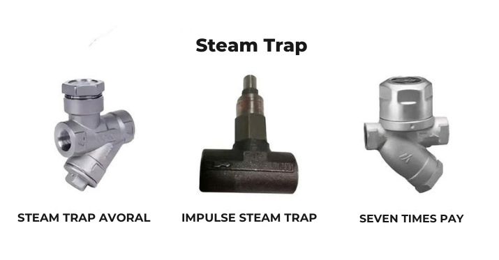
Thermodynamic steam traps
Thermodynamic steam traps operate based on differences in flow characteristics between steam and condensate. Condensate has higher density and lower velocity, so it easily passes through the trap, while high-velocity, high-pressure steam creates a force that closes the disc. The continuous switching between these two states creates the characteristic open–close cycle of thermodynamic traps.
Advantages:
- Simple, robust construction
- Withstands high pressure
- Reliable and low-cost
Disadvantages:
- Sensitive to cold winds and vibration
- Can exhibit unstable opening and closing when condensate load fluctuates rapidly
- May pass some steam during certain cycles, causing a “clicking” noise
Applications:
This type is suitable for small drain points, ends of steam lines, draining steam headers, removing condensate on long main lines, and locations without steam flow control valves. It is also a popular choice for high-pressure systems and harsh operating environments.
2. Thermostatic steam traps
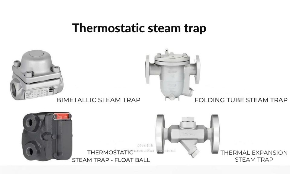
Thermostatic steam traps
Thermostatic steam traps operate based on thermal expansion of a sensing element, usually a bimetallic strip or bellows. When hot steam enters, the element expands and closes the valve to retain steam. When cooler condensate enters, the element contracts and the valve opens to discharge condensate and non-condensable gases.
This type discharges condensate based on temperature, vents air very well, and has a compact design. However, it is not suitable for rapidly changing loads. Thermostatic traps are commonly used at the outlets of small heat exchangers or in locations where only cooled condensate is to be discharged.
3. Mechanical traps (float and inverted bucket – overview)
Mechanical traps operate based on changes in water level and density differences between steam and condensate. When condensate rises, the mechanical mechanism opens the valve; when steam enters, the valve closes. This group offers accurate and stable condensate discharge.
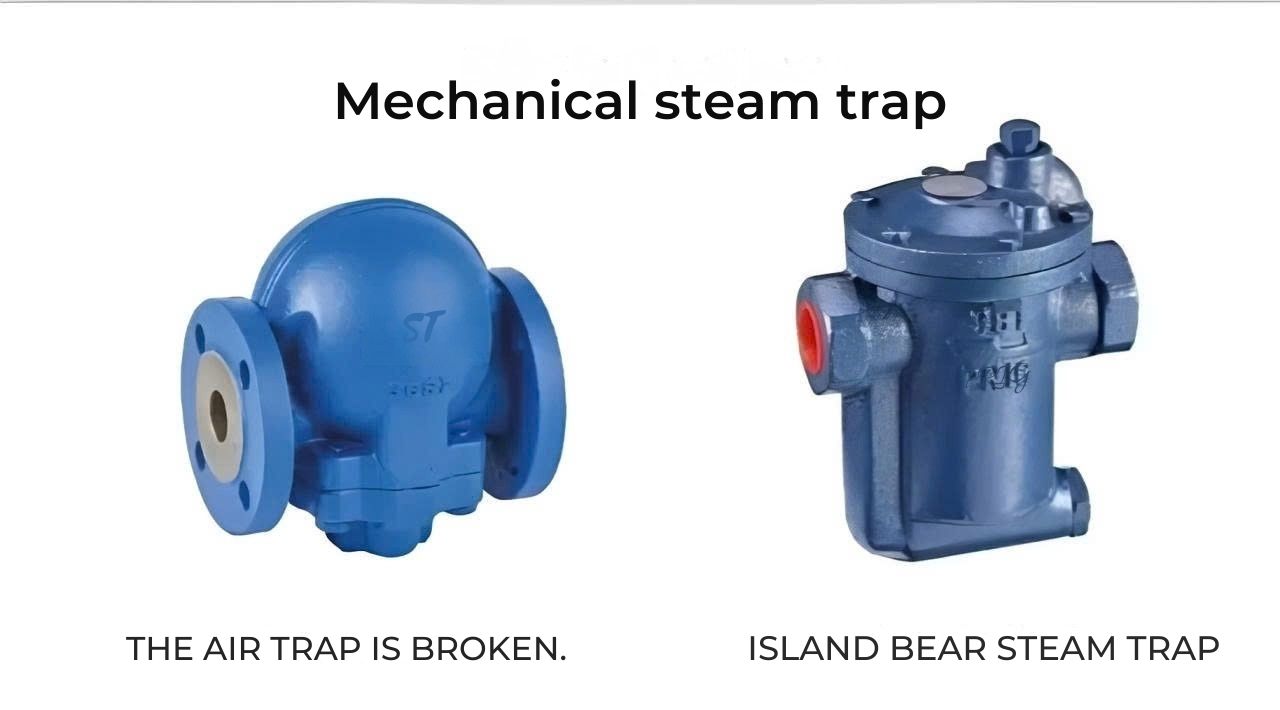
Mechanical traps
3.1 Inverted bucket trap
The inverted bucket trap uses a hollow bucket to control the discharge valve: steam entering causes the bucket to float and close the valve; when condensate fills the body, the bucket sinks and opens the valve. This type discharges intermittently in cycles and is suitable for equipment with stable loads and steady condensate production. However, it should not be used on equipment with strongly fluctuating loads or where continuous discharge is required, as it can cause condensate buildup and reduced heat-transfer performance.
3.2 Float trap
The float trap uses a ball float to sense the water level in the trap body. As condensate increases, the float rises and opens the valve; when steam enters, the water level drops, the float descends, and the valve closes.
Float traps discharge continuously and are very effective for equipment with large condensate loads, strongly variable loads, or modulating steam control valves. However, they are not suitable for very high steam pressures, locations with limited installation space, or small drain points on main lines.
4. Orifice / Venturi devices
Orifice or Venturi devices are essentially fixed restriction orifices without moving parts like conventional steam traps. Their key advantage is extremely high durability with minimal maintenance. However, a critical drawback is that if the orifice is not sized correctly or the system has highly variable loads, they can easily cause flooding in heat exchangers or continuous steam leakage, leading to energy losses. Therefore, orifice devices should be used selectively and cannot completely replace standard steam traps (float, inverted bucket, thermodynamic) in industrial systems.
III. Guidelines for proper steam trap station installation
1. General principles
In a properly designed steam system, steam always enters the heat exchanger from the top, while the steam trap must be installed at the bottom to collect condensate after heat transfer. The trap location must be lower than the condensate outlet so that condensate can flow by gravity, preventing accumulation in the equipment.
For some special equipment with unique designs, the installation position may differ, but the most important principle is that condensate must not be trapped in piping or inside equipment, as this reduces heat-transfer efficiency and creates a risk of water hammer.
2. What does a standard steam trap station include?
A standard steam trap station typically consists of:
- 1 steam trap
- 2 isolation valves (upstream and downstream)
- 1 bypass valve for cleaning/maintenance without shutting down the system
- 1 check valve downstream if the condensate line is shared
- 1 sight glass (if needed) to monitor trap operation
- 1 strainer upstream of the trap (even if the trap has an internal strainer, an external one is safer)
3. Common installation errors (ignoring “water flows to the lowest point”)
Common misinstallation and how to fix it:
- Trap installed high while a lower section of pipe holds condensate → air binding, waterlogging, poor or no operation
- Condensate retained in the pipe → reduced heat-transfer surface and lower efficiency
- Steam and water mixed → water hammer, piping vibration, risk of damage
Solution:
- Install drain points at the lowest spots and place traps there, or
- Use a dip tube or inner tube to draw condensate from the lowest point into the trap
4. Correct orientation and flow direction
Correct installation practices:
- Always follow the flow direction arrow on the trap body
- Float traps are designed for horizontal installation; do not rotate the float chamber downward against the design
IV. How to select the right steam trap type and sizing
1. Choosing the trap type by application
Selecting the correct steam trap for each location is critical to ensure effective condensate removal, maximum steam retention, and stable operation.
- Equipment with modulating steam control valves and variable loads → use float trap + thermostatic trap (continuous discharge, good air venting)
- Equipment with stable loads → use inverted bucket trap
- Drain points without control valves (draining steam headers, removing condensate from steam mains, etc.) → use thermodynamic / disc traps
- Equipment requiring discharge only when condensate cools → use thermostatic traps
By selecting the correct trap type according to load characteristics, operating conditions, and condensate discharge needs of each piece of equipment, businesses can optimize heat-transfer efficiency, reduce steam loss, and significantly reduce fuel costs. This is key to achieving reliable, safe, and long-term high-performance steam systems.
2. Determining condensate discharge capacity and safety factor
To select the right steam trap and ensure stable condensate removal, calculating condensate load and choosing an appropriate safety factor is essential.
- Determine design condensate load (L/h, kg/h)
- For continuously varying loads → use a safety factor of 2–3 times
- For stable loads → use a safety factor of about 1.5 times
If the selection is too close to the design value:
- Trap cannot discharge all condensate → waterlogging, slow heat-up, lower efficiency
- Operators open bypass lines to “heat faster” → major live steam loss
Applying the correct safety factor helps avoid waterlogging, ensures faster heat-up, and prevents steam loss due to frequent bypass usage—a major source of energy waste in factories.
3. Sizing by differential pressure ΔP
ΔP = pressure before the trap – pressure after the trap
For condensate to return to the boiler, it must overcome:
- Static head (elevation)
- Friction losses in piping, elbows, fittings
- Losses across valves, strainers, traps, check valves, etc.
Example:
5 m elevation (~0.5 bar) + 100 m main condensate line (~0.5 bar) + trap/equipment group losses (~4 bar) → require ~5 bar inlet pressure, ΔP ~4 bar.
4. Example using a capacity chart (FT14 – PMO10/14)
-
- X-axis: ΔP (bar); Y-axis: capacity (kg/h)
- Select ΔP = 5 bar and find intersections with PMO10, PMO14 curves
Note: The higher the PMO rating, the smaller the orifice generally is, so at the same ΔP, the capacity is lower than a lower-PMO model.
Discharge capacity:
PMO14 line ~350 kg/h PMO10 line ~700 kg/h → choose FT14/PMO10 to get a capacity ~3 times the 200 kg/h requirementV. Common steam trap problems and mistakes
1. Selecting the wrong trap type
- Using mixed types randomly: disc trap here, inverted bucket there, float trap elsewhere for similar equipment
- Wrong mindset: “a trap is a trap” → system runs poorly, difficult to diagnose problems
2. Incorrect condensate capacity
- Not understanding that downstream pressure must be sufficient to overcome condensate return backpressure
- Selecting trap based on ΔP lower than actual → actual discharge capacity drops → condensate not fully removed
3. Ignoring ΔP (differential pressure)
- Not understanding that downstream pressure must be sufficient to overcome condensate return backpressure
- Selecting trap based on ΔP lower than actual → actual discharge capacity drops → condensate not fully removed
4. Installing traps in the wrong location (not following “water flows to the lowest point”)
- Installed high with a low point below holding condensate → air binding, waterlogging, water hammer, lower efficiency
- No drain point at the lowest section
5. Not venting non-condensable gases
- No deaeration system or no traps with automatic air venting
- O₂ and CO₂ accumulate in equipment → block heat transfer and cause corrosion
6. Using one trap for multiple machines
- One machine drains properly, others do not → uneven temperature between machines
- Cause: cutting cost, lack of understanding
- Principle: each machine must have its own steam trap.
7. Incomplete trap station accessories
- Only a trap + one isolation valve; no strainer, no check valve, no bypass
No strainer → debris jams the trap, causing continuous steam blow or no discharge - No check valve → condensate backs up between equipment, causing temperature fluctuations
8. No separator on main steam lines
- Long steam mains with no separators and no drain points
- Condensate collects at the equipment or direction changes → water hammer, vibration, reduced efficiency
- Recommendation: every 30–50 m, provide a drip leg + trap set; ideally use a separator (drying steam to ~95%).
9. Incorrect trap orientation and direction
- Installed against the flow arrow, may still work but inefficient
- Float traps installed in the wrong position
- Result: out-of-spec operation and premature failure
10. No steam trap inspection and maintenance program
- Many factories never clean/inspect traps
- Boiler + traps account for ~80% of steam production cost → ignoring them is extremely risky
- Replacing low-quality traps with high-quality ones often has payback < 3 months
11. Frequently opening bypass valves to “heat faster”
- Opening bypass → condensate bypasses the trap and steam flows directly into the condensate line → massive steam loss
- Acceptable as a temporary emergency measure, but if it becomes a habit, trap sizing and selection must be reviewed
12. Combining high-pressure and low-pressure condensate returns
- Using different steam pressures (e.g., 8 bar for dryers, 4 bar for ironers) but combining condensate into a single return line
- High-pressure side pushes into the low-pressure side → low-pressure equipment underperforms or doesn’t work
- Solution: separate condensate lines for high pressure and low pressure, then combine before returning to the boiler.
FAQ – Common Questions About Steam Traps in Industrial Steam Systems
1. Why do steam traps have such a big impact on fuel consumption
A properly operating trap retains steam to complete heat transfer and only discharges condensate. If the trap is faulty or incorrectly sized, condensate accumulates and steam loss increases, forcing the boiler to burn more fuel to make up for lost energy.
2. What is the difference between thermodynamic, thermostatic, and mechanical traps?
Thermodynamic traps open and close based on steam velocity.Thermostatic traps open and close based on temperature.Mechanical traps open and close based on water level. Each type suits different applications and must be selected according to load, flow, and operating characteristics of the equipment.
3. Can orifice/Venturi devices replace traditional steam traps?
No. An orifice is just a fixed restriction and does not open or close according to load. Even though it is durable and rarely fails, it can cause flooding or continuous steam loss if incorrectly sized or if load changes significantly. It should be used selectively and cannot completely replace float, inverted bucket, or thermodynamic traps.
4. How do I choose the correct discharge capacity for a steam trap?
Determine design condensate load and select the safety factor:
- Variable load → 2–3 times
- Stable load → about 1.5 times
Choosing a trap that is too small will cause waterlogging, force frequent bypass use, greatly increase steam loss, and reduce equipment efficiency.
5. Why is ΔP (differential pressure) so critical when selecting a steam trap?
ΔP determines the ability to push condensate back to the boiler. If the trap is selected based on a ΔP lower than the actual value, the discharge capacity drops significantly → waterlogging and poor heat transfer. You must account for static head, pipe friction, and losses across valves, strainers, and traps to select the correct ΔP.
VI. Conclusion
Steam traps play a pivotal role in ensuring that steam systems operate stably, save fuel, and maintain high heat-transfer efficiency. Understanding their function, selecting the right type, and installing them at the correct locations will help avoid steam loss, reduce condensate buildup, and extend equipment life.
By optimizing steam traps correctly, businesses can significantly reduce operating costs and improve the safety of the entire system. If you need more detailed guidance for specific applications, please get in touch for support.
Related Articles:
Additional Reference Videos:
[DIVI] Reveal interesting things from steam boilers from the steam room for newcomerse
[DIVI] Boiler safety and practices for safe operation
DIVI Group's Boiler Products:
Other news
-
Steam Separator – An Effective Solution for Dry Steam
29/12/2025, -
Treating High CO Emissions in Fixed-Grate Boilers – Is Boiler Replacement Necessary? Practical Solutions from DIVI
18/12/2025, -
COMPARISON OF STEAM TRAPS: PRINCIPLES – EXPERIMENTS – OPTIMAL SELECTION FOR STEAM SYSTEMS
29/11/2025, -
Compact Biomass-Fired Boiler DVG-VN – The Optimal Fossil-Fuel Replacement Solution for Factories
23/11/2025, -
Which Boiler Should You Choose: Fixed Grate or Fluidized Bed? Detailed Efficiency, Cost & Environmental Comparison
24/06/2025, -
5 Common Mistakes in Industrial Steam Distribution Systems
11/06/2025, -
Mr. Boiler Speaks: Wake-Up Call from an Industrial Icon
09/06/2025, -
What is a Thermal Oil Heater? Structure, Benefits & Safety Tips
27/05/2025, -
3 Danger Signs of Boiler Operation You Should Never Ignore
24/05/2025, -
7 Common Causes of Boiler Flue Gas Issues – Effective Treatment Solutions
08/05/2025,
DIVI GROUP CO., LTD
Office: 588 Pham Van Chieu street, ward 16, Go Vap district, Ho Chi Minh city, Viet Nam
Factory: Khanh Binh 10 street, Khanh Van quarter, Khanh Binh ward, Tan Uyen city, Binh Duong province, Viet Nam
Hotline: +84 942 488 818
Tel: 0274 3800 338
Email: info@divigroup.com.vn
Business license : 0311016524, issue date : 26/07/2011 by Department of Planning and Investment of Ho Chi Minh City
Representatives: Lê Văn Hiếu
Online :
Vistited :